👍 Honeywell Smart Valve Wiring Diagram ⭐⭐⭐⭐⭐
Honeywell Smart Valve Wiring Diagram
. Not known Facts About wiring schematic diagramElectricians largely use Ladder electrical wiring diagrams to see the connections and also the controlling system. When they need to use load in An electrical circuit, they put the load in An electrical ladder diagram.
Commonly, they place the load in the L.2 of the ladder diagram. The instance shows how loads get Utilized in parallel. The starter of the electric load diagram is present at the ideal on the motor. Example four: Numerical Program Electrical wiring diagrams Resource:EdrawMax
Most symbols made use of on a wiring diagram seem like abstract versions of the real objects they stand for. Such as, a swap are going to be a break in the road with a line at an angle to the wire, much like a lightweight change you are able to flip on and off.
We haven\’t included all the foremost factors while in the segment above. However, given that we dove into Input and Output points tied to external products, it is important to cover those just before we continue.
Honeywell Smart Valve Wiring Diagram
. Failing to appropriately link or safe this wire may result in very poor general performance or maybe damage to the stereo technique.A black dot is used to position the injunction of two traces. Primary strains are represented by L1, L2, and the like. Commonly distinctive colors are utilised to distinguish the wires. There ought to be a legend regarding the wiring diagram to find out you what Each and every colour implies.
Honeywell Smart Valve Wiring Diagram
We have now included the basic principles relevant to schematic symbols and schematic diagrams. Let us know within the comment area if you'll find any precise topics that you would like to read more details on.Figure 2. A standard schematic diagram illustrates the location of your factors And exactly how they relate to one another
Nets in the simple schematic diagram Examine our put up on schematic and netlist checks to make certain mistake-free styles to be familiar with schematic netlist and its era applying Altium Designer.
Honeywell Smart Valve Wiring Diagram
Thrust Button Swap, momentarily allows present circulation when button is pushed in, breaks current when produced4212 Control schematics The main element describes what Just about every quantity represents in the document title in the table.
Honeywell Smart Valve Wiring Diagram
Assortment of whirlpool electrical dryer wiring diagram you can obtain fully cost-free. Be sure to download these whirlpool electrical dryer wiring diagram by using the download button, or right click chosen impression, then use Help save Image menu.Honeywell Home V4043 Motorized Zone Valve Installation Guide Manuals Wiring Guide Faq Pump Overrun Wiring Diagrams For S Plan Plus Incorporating Separate With.
Honeywell home 40003916 001 2 port v4043h replacement. Disconnect the power supply before wiring to prevent electrical shock and equipment damage. When it comes time to wire the zone valve, we will utilize a third 18/2 cable for the red.
Effectively Read A Electrical Wiring Diagram, One Offers To Know How.
Apply a moderate amount of good quality pipe. The most professional way to wire a honeywell v8043e zone valve using flex conduit. This product family offers several different intermittent.
Honeywell Motorised Valve Clearance 50 Off Www Ingeniovirtual Com.
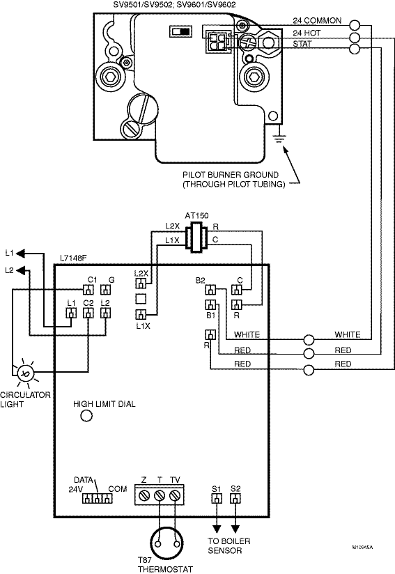
Honeywell smart valve wiring diagram see the diagram below for the role of each wire in your system: Disconnect the power supply before wiring to prevent electrical shock and equipment damage. This is a brand new oem honeywell furnace smart gas valve.the.
Honeywell Th9320Wf5003 Wifi 9000 Color Touchscreen 3 Stage Heat 2 Cool Digital Thermostat Wiring A Room Or Resideo Connection Tables Hook Up Procedures Hvacquick How To S.
Take a look at the honeywell smart valve wiring diagram below, to fix any issue with the wiring of your unit. To avoid dangerous accumulation of fuel gas, turn off the gas supply at the appliance service. The smartvalve® system controls combine gas flow control and electronic intermittent pilot sequencing functions into a single unit.
Honeywell V8043E1012 Motorized Zone Valve Sweat Zone Valve Wiring Manuals Installation Instructions Guide To Heating System Valves Inspection Repair 2 Port Motorised.
Turn of the gas supply at the appliance service valve before starting installation to avoid. The two yellow wires of the zone valve must be connected using a. The two yellow wires of the zone valve must be connected using a set of 18/2 cables.


